Table of Contents
Motorcycle Switching USB Power Supply Updated
1. Overview
There are numerous commercial offerings for motorcycle USB power adapters. All the ones I found have two potential issues:
- Weather resistance provided only by a fragile-looking rubber cap
- They are likely using linear regulators, since those are cheaper
There are many reasonable options for weather resistant connectors. My personal favorite is the Deutsch DT / DTM connectors (and the cheaper Amphenol copy), readily available from electronics suppliers such as Mouser and Digikey and from Batts Racing.
The problem with linear regulators is that they waste power as heat.
Ideally, we want a more efficient switching power supply to save a
couple amps of charging current. There are a few descriptions online
about using an LM7805 to build a USB charger; however, this is a
linear regulator. Instead, we can use a
OKI-78SR ,
which is a 5V switching power supply with a wide (7V-36V) input
range. This regulator costs less than 5USD from electronics suppliers
such as Mouser and Digikey.
,
which is a 5V switching power supply with a wide (7V-36V) input
range. This regulator costs less than 5USD from electronics suppliers
such as Mouser and Digikey.
2. Circuit Diagram
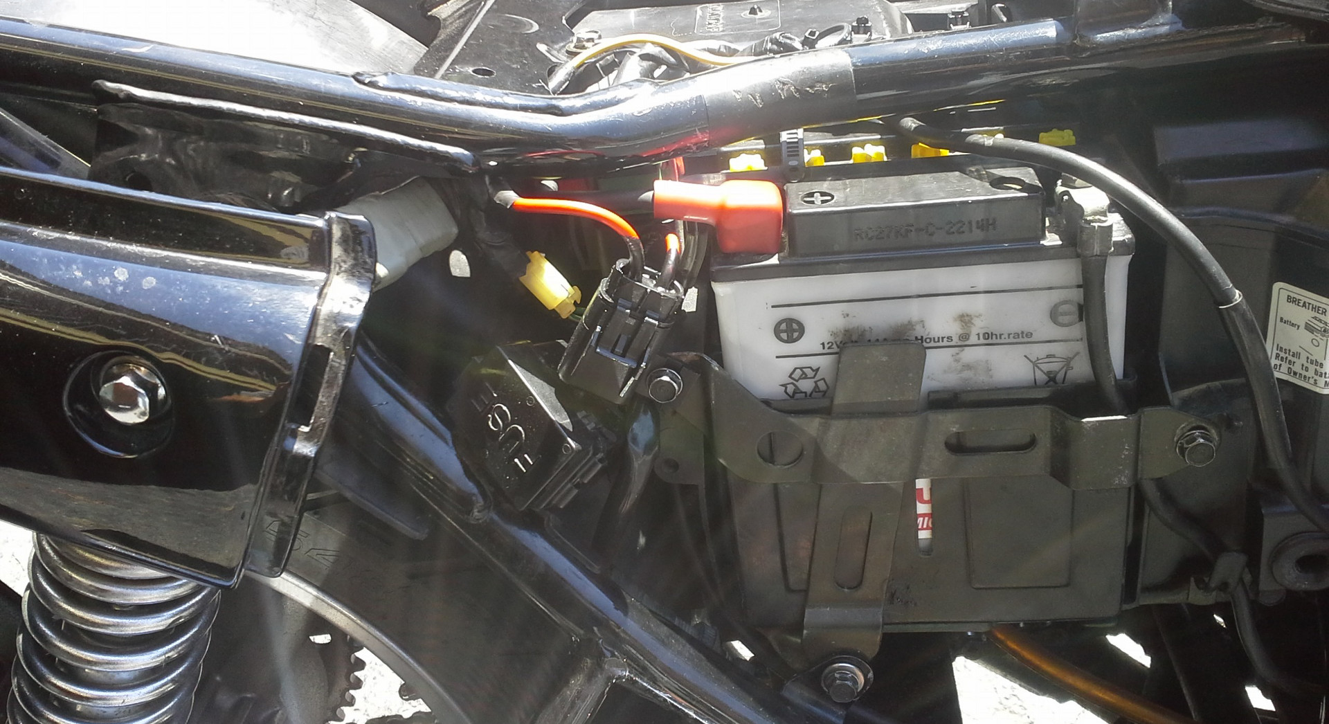
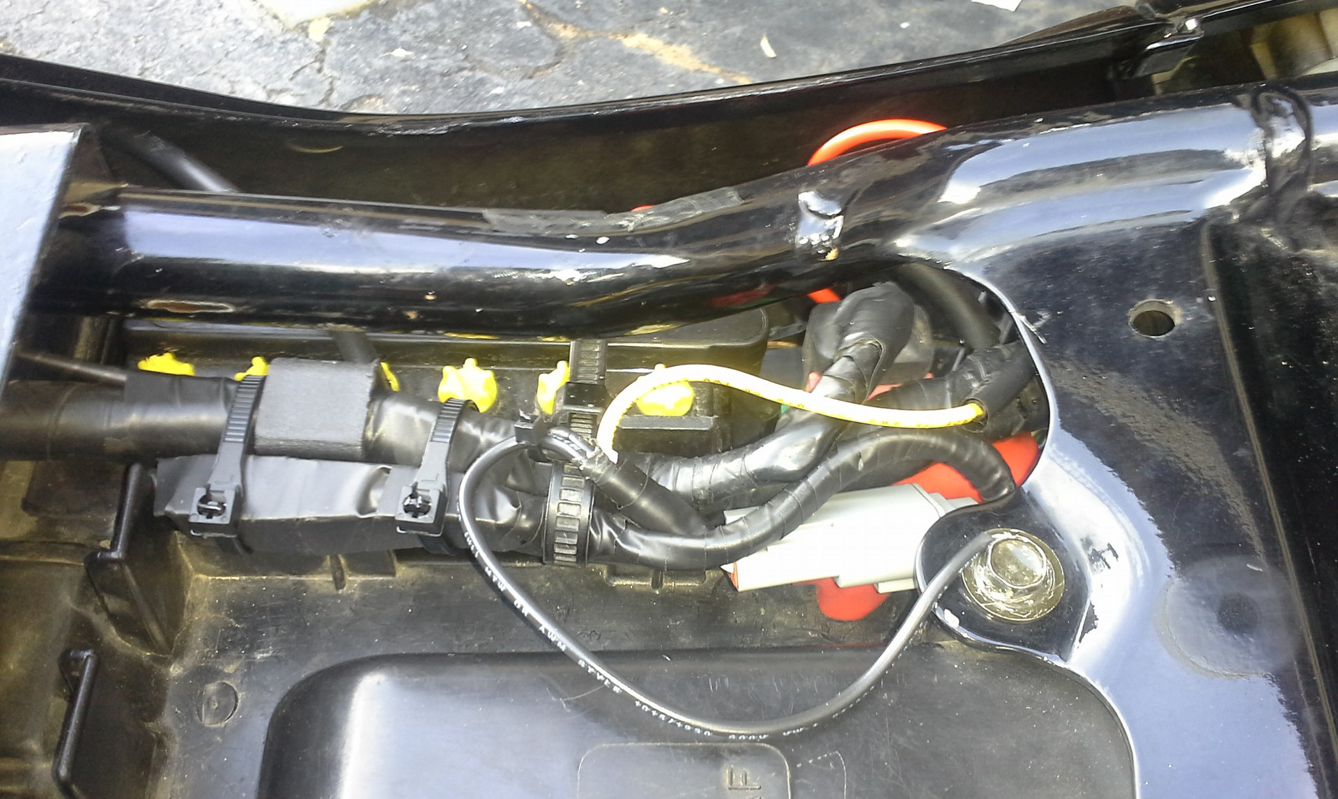
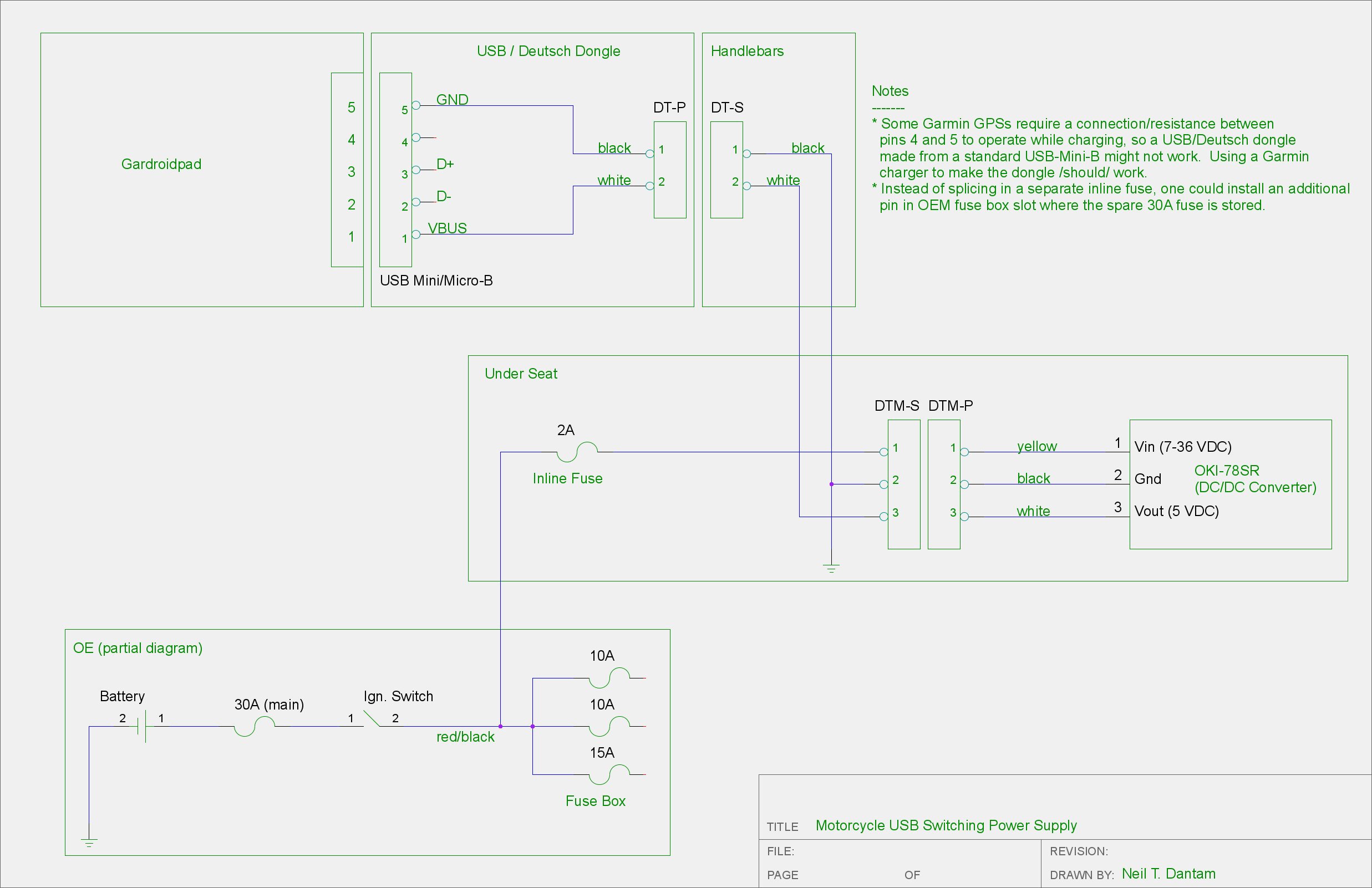
Here is how I wired the power supply into my '97 CB750:
2.1. Parts
- OKI-78SR
- Inline fuse holder OR extra pin for fuse box
- 2A fuse
- Wire
- Wire splices
- Electrical tape
- .1" pin sockets
- Solder
- Cable ties
- Cable sleeving
- Waterproofing (see below)
- Electrical Connectors (see below)
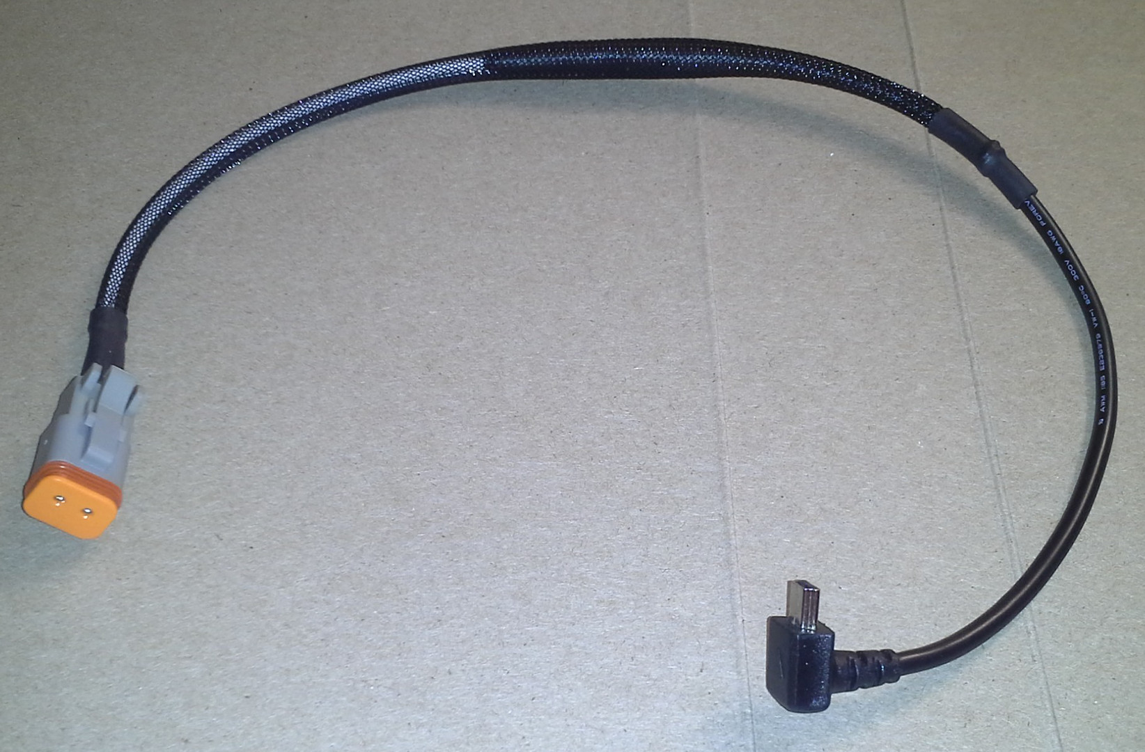
- USB mini/micro cable for dongle (see Garmin note in diagram)
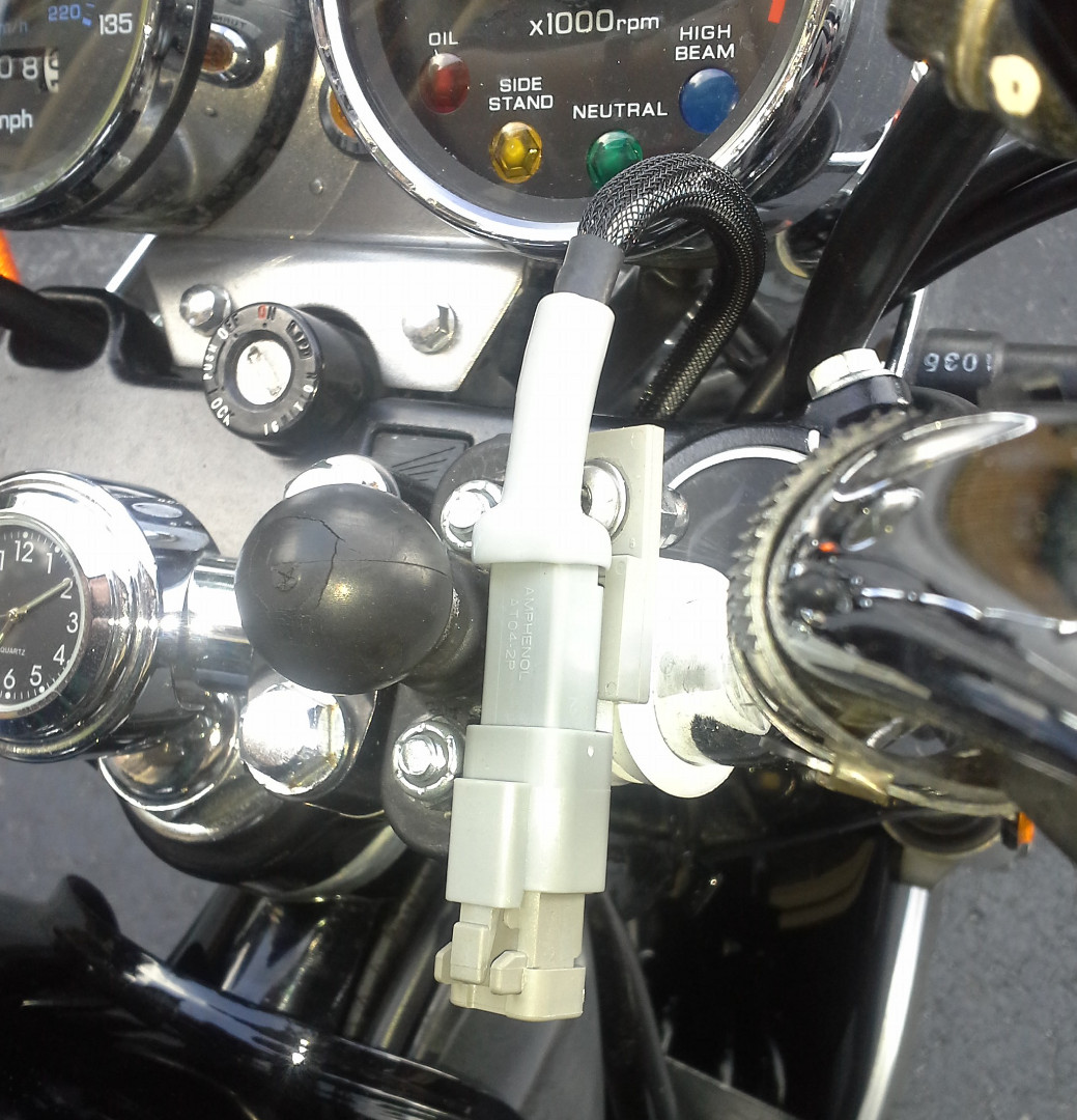
- (optional) P-clamp to mount handlebar connector
2.2. Tools
- Multimeter
- Wire cutter
- Wire stripper
- Crimper with appropriate dies
- Soldering Iron
3. Installation Notes
3.1. Splicing
The general advice for vehicle wiring is to crimp rather than solder, because soldered wires are more likely to crack due to vibration and fatigue. Make sure you use a decent crimper – ratcheting ones are nice – with a die to match your splice connectors, e.g., open barrel, uninsulated, insulated, or heat-shrunk.
3.2. OKI-78SR
To connect the OKI-78SR PSU, I crimped some .1 inch pin sockets onto the wires, and then soldered the sockets onto the PSUs pins. This avoided mounting the PSU on a separate board. Still, there may be a better way.
3.3. Waterproofing
To waterproof splices you can use:
- Adhesive-filled heatshrink tube
- Self-fusing tape
- "Liquid electrical tape"
To waterproof the OKI-78SR, I wrapped it in electrical tape and then coated it with RTV silicone. Seemed to work well enough, though I didn't try the immersion test. The best way would probably be to "pot" the board in silicone or epoxy filled enclosure.
3.4. Wire
Automotive primary wire would probably work just fine, but I worry about corrosion and fatigue. Marine-grade wire is tinned to resist corrosion and claimed to resist fatigue due to vibration and flex.
3.5. Connectors
The OE connectors on the Honda Nighthawk don't offer much in the way of weather resistance, but there are numerous alternatives.
Deutsch DT / DTM connectors (and the cheaper Amphenol copy) are waterproof, rugged, and reusable (minus the crimped pins). They are used in motorsports, construction equipment, and are even original equipment on a few motorcycles. Stamped pins for the Deutschs are cheaper than the solid pins, especially when including the price of the crimper. You can use a standard open-barrel crimper on the stamped pins.
Weather Pack connectors are another option, but I think the Deutsch's are nicer.
4. Photos